Basic 101 on bilge pumps?

quote:

Originally posted by Double D

quote:

Originally posted by Cam

quote:

Originally posted by Radioactive
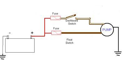
Battery-drawing-Bilgepump-v3.jpg


Bingo. We have a winner here.


Why 2 fuses ??

What is protecting the wire from the battery to the first and second fuses wired that way ??

edit.......the one thing correct with that drawing is the color of the wire from the battery to the fuses....being RED indicates fire.


Don,
The red wire is the 12v feed, like many other items on the boat, they all need the 12v feed to work.

So back to your question, "Why 2 fuses?

My response is why not?

Here is why I say that.
You have two feeds for two different purposes, if you use one fuse for both feeds, and one feed goes bad, you lost both feeds. In other words,the float shorts out, manual discharge is now also in the mud.

Guess what I am saying is we have two ways to dump water, if you protect both ways with one fuse and that fuse goes, you lost your redundancy, or override?

Think I now get how this was wired in my boat, will confirm, but think all comes from one power source.
 
quote:

Originally posted by Double D

If the single fuse is properly sized it will protect the circuit. I don't see the need for multiple fuses on any one circuit. Just like in house wiring there is one breaker per circuit.....you never have a branch circuit in the panel box ....then another fuse before each device. Makes no sense.


In a house, do you run the oven, stove top, washing machine and dishwasher on a single circuit breaker sized to carry all 5 loads together? Obviously not so why would want to run 4 or 5 bilge pumps on a single oversized fuse?

And just as important bilge pumps are life saving equipment. If one of multiple pumps or switch fail and trip the fuse or CB, do you want to loose he other ones too? I don't.... Hence the preference for having each on a separate circuit with its own protection. Common sense... A lost art.
 
Double D is correct, the fuse should be mounted as close as possible to the power source, not down line of the split. In the above schematic, if flooding were to occur and the operator closed the manual switch, then both switches would be closed. If the motor seized and over drew, it would require both fuses to blow to protect the power wire. Since you have branched the circuit, the fuses would be slow to blow or not blow at all because the current would be split between the two. By not blowing within the specified time you have endangered protective qualities of the insulation on the power wire. What you have effectively done in this schematic is made the power wire a bus and as such you either have to protect the bus with an appropriately sized circuit protection (three fuses) or a C/B on the power wire and fuses on the branch circuit. On an aircraft there is no way the schematic above would be approved.
 
"In a house, do you run the oven, stove top, washing machine and dishwasher on a single circuit breaker sized to carry all 5 loads together? Obviously not so why would want to run 4 or 5 bilge pumps on a single oversized fuse?"

In a house you have a main breaker which protects the bus (the panel) then the branch circuits. Always protect the bus first then the circuits! Your power wire is the bus.
 
Don,
The red wire is the 12v feed, like many other items on the boat, they all need the 12v feed to work.

**************************************************

Walter.... I understand that and your right. It was just my attempt to be sarcastic....( red being fire ). The reason I question why 2 fuses on the one circuit....the least amount of fuses or splice connections the less chance of failure of that circuit. The idea of 2 separate fused feeds from the battery would be another possible way to wire it . One fused feed to the dash switch....and one fused feed to the float switch.....then as the drawing shows....switches to the pump.
 
Didn't read much past the first post, too much to read, but if any of it relates to the best float switch - stop right there. None of them are worth two damns. Look into Water Witch switches. Nothing to wear out, nothing to jam up. Best solution there is short of a live watch for a high water alarm or bilge pump switch.
 
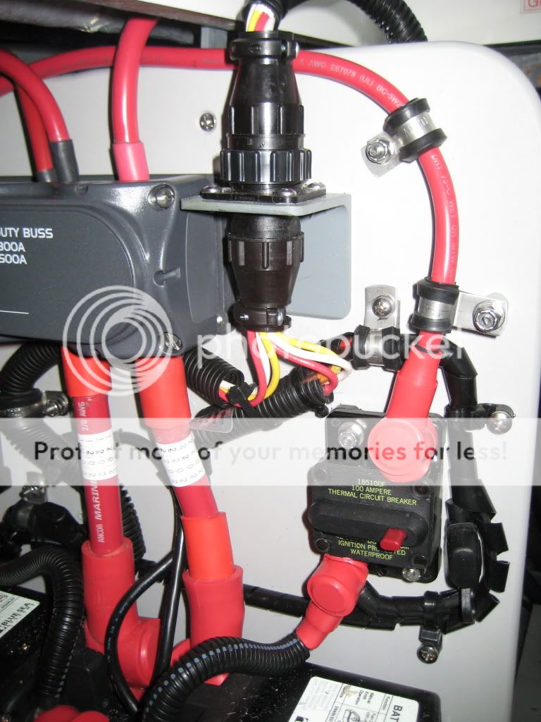
Walter, my Silverton has a circuit breaker for each pump in addition to fuses. For the Silverton 330, under the transom locker, if you look up from the engine room, there is a circuit board with the breakers there for each bilge pump and a few other things such as the battery parallel, the solenoid is here too. Looks like the breaker in this pic.

IMG_0490.jpg
 
That is my boat. Nice you bring up that example :). The 100 amp breaker there protects the hot bus. I have two hot busses and a 100 amp breaker protects each one. From the hot busses, the bilge circuit (one wire) goes out each protected by their own breaker. Thus I have fulfilled the requirement to protect the bus first (note it is very close to the battery) and then the branch circuits by a single device.
 
My Sea Ray has a separate 10 amp breaker for each of it's three bilge pumps, and another 10 amp breaker for the emergency bilge pump, or a total of 4 separate bilge pump breakers.
They are located in the bilge.
All of the bilge pumps have float switches, and all but the emergency bilge pump have manual toggle switches that also turn them on.
The float switches and toggle switches all work with the battery switches in the off position.
Are the batteries good? Is it just the one pump that isn't working, or are they all out?
I've had float switches go bad on me, but the pump still worked with the manual switch. The way my boat is wired, the float switch can get power from either the float switch or the manual switch.
I've never had a breaker for any of the bilge pumps trip. But since your pump is good, and you seemingly aren't getting power to it from either the float, or manual switches, then maybe something made the breaker trip.
A 12 volt test light is a valuable tool to keep on the boat, and they are cheap.
If you get hold of a test light and can get access to the manual switch for the bilge pump you can check to see if you are getting power to the switch. If so, flip the switch and see if you are getting power going out of it. If you are getting power out of the manual switch, then keep it in the on position and see if you have power at the pump itself. You can also do these checks in reverse if it's easier.
If you have no power to the manual switch, then you need to check the breaker. It's not impossible for a breaker to fail. I've never had one for a bilge pump fail, but I have had others act like they failed because of a green (weather) connection.
It's pretty easy to check them. Just do the same as you would to check a switch.
 
Fact is, that happened to me. My ultra switch is 16 years old and has survived two pumps.
 
The Ultra switches that are referenced are Reed Switch technology. In a previuos life I was a Mfg Engineer for a competitor who's main product was sold to the US Navy shipyards, and all of my boats, lol.

The switches are made with two pieces of metal that overlap in the middle. These contacts are enclosed in a glass tube and have external contacts on each end. They look very similar to a glass tube fuse. These switches are encapsulated in some kind of RTV or epoxy and are located within the center shaft of the assembly. The "donut" is a buna-n float (or other material based on the liquid) which has magnets epoxied within. The float rises and falls around the stem and the magnetic cicuit opens or closes the "reeds" within the glass switch thereby opening or closing the circuit.

About the only issue with these is the current limits placed on the switches, most mfg go thru a relay and may have a timer to reduce cycling in rough water.
 
Back
Top